Kirchhoff's Laws and Circuit Analysis
Apply Kirchhoff's current and voltage laws to analyze complex circuits and solve for unknowns.
Why this shows up in the exam
NEET expects you to use Kirchhoff's laws for multi-loop and multi-junction circuit problems.
How NEET tests this
Learn the idea
Kirchhoff's laws state that at any junction the algebraic sum of currents is zero and around any closed loop the algebraic sum of potential differences is zero, enabling analysis of complex circuits.
🧠 Memory hook: KCL KVL – Current In = Current Out, Voltage Round = Zero
Get this one clearly and it pays off every single time it shows up in the paper. 🎯
Formulas & facts to keep ready
- Kirchhoff's Current Law: sum of currents entering a node equals sum leaving
- Kirchhoff's Voltage Law: sum of emf's and potential drops around a closed path is zero
- Resistors in series carry the same current and their resistances add
- Resistors in parallel have the same potential difference and reciprocal of total resistance is sum of reciprocals
- For a uniform wire resistance is proportional to length, so each side of a 4 Ω square loop is 1 Ω
How to approach it
- 1Identify all distinct nodes and independent loops, assign a direction to each current
- 2Write KCL equations at each node and KVL equations for each independent loop
- 3Use series‑parallel reduction where possible, solve the simultaneous equations for the unknown currents or voltages
Common slip-ups that cost marks
- •Incorrect sign for voltage drops while applying KVL
- •Treating a bridge resistor as automatically series or parallel without checking its connections
🌟 That's the whole idea — you've got this. Try the practice set below; every question you attempt makes it stick a little harder.
Practise it
These are real questions from past NEET papers that test this exact idea.
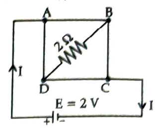
A uniform metallic wire having resistance 4 Ω is bent to form a square loop (ABCD) (see figure). A resistance of 2 Ω is connected between points B and D and a battery of 2 V is connected across points A and C, as shown in the figure. Now the value of current (I) is: [Image of a square circuit ABCD with a 2Ω resistor between B and D, and a battery E=2V connected across A and C. Current I flows from the battery.]
Push further
More challenging1 harder question built from the past papers above — a step up in difficulty, with distractors designed so you can't get there by elimination. Written and checked by our reviewers, not from a real paper.
Consider a circuit segment with a 10V battery and a 5 Ohm resistor. If the current flowing through the resistor is 1A from point M to point N, and point M is at a potential of 15V, what is the potential at point N? The negative terminal of the battery is connected towards point M, and its positive terminal towards point N.
More from Current Electricity
Resistivity, Conductivity, and Material Properties
Learn how resistivity and conductivity depend on material, length, area, and how resistance changes with dimensions and temperature.
Series and Parallel Combinations of Resistors
Master the calculation of equivalent resistance, voltage division, and current distribution in series and parallel resistor networks.
Electrical Energy, Power, and Heating Effect
Calculate electrical energy, power dissipation, and understand the heating effect of current in various circuit configurations.
EMF, Internal Resistance, and Terminal Voltage
Understand the concepts of EMF, internal resistance of cells, and how terminal voltage is affected in real circuits.
Drift Velocity and Microscopic View of Current
Explore the microscopic origin of current, including drift velocity, relaxation time, current density, and the effect of electric field in conductors.
Wheatstone Bridge and Meter Bridge
Learn the principle and application of Wheatstone and meter bridges for measuring unknown resistances.